|
|
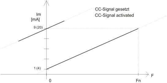
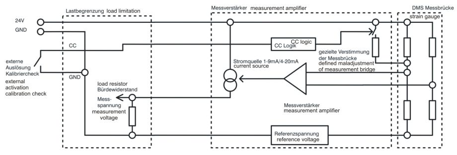
calibration check signal  The calibration check signal is a low-active digital signal which can be used to generate a defined maladjustment of the measurement bridge. Before designing the force transducer the amount of maladjustment from zero point can be defined within the range of amplifier input signal. It is recommended always to use an amplifier with current output because current signals are less sensitive to disturbances than voltage signals. If the measurement electronics requires an input voltage, an appropriate load resistor can be inserted in the input of the measurement electronics. With the zero point current which is greater zero, checking of the cable is carried out. Using a force transducer with internal calibration check (CC), the connection of the CC contact with ground (GND) forces the signal current of full load (e.g. 9 mA or 20 mA) at the output of the amplifier, where the sensor is unloaded. This is useful for testing proper functioning of the switch off mechanism of calibration without loading the sensor. It is checked:see figure 1 (on the top): Characteristic diagram of a sensor with calibration check. Example for the use of calibration check signal for checking the switch off chain:  Figure 2: Functioning chain with external calibration check activation of a VELOMAT measurement amplifier. Activation of the calibration check signal results in a defined increase of the measurement amplifier output signal corresponding to a defined maladjustment of the sensor. Since this increase achieves the maximum value of the sensor current, the switch off relay has to switch over into the overload state. With this method the switch off chain can be checked by means of an external unit or by manual inspection. · correct connection to strain gauge measurement bridge · Functionality of measurement amplifier · Switch off function of load limitations · correct external wiring of switch off circuits Hint: As needed the calibration check signal can also be exploited for online monitoring of the sensors. For this application the measurement range has to be chosen wide enough. For example, a sensor with amplifier 4…20 mA: By loading the sensor, 20 mA are measured on the output. Adding the CC signal, a 16 mA step and hence a measurement signal of 36 mA is obtained. => If the signal of 36 mA is within the measurement range, online monitoring of sensors with amplifier is possible! Example for determining the required measurement range: Sensor with amplifier 4...20 mA => CC-signal generates a step of 16 mA => 4 mA zero point + 16 mA CC step = 20 mA For possible questions or further hints we are at your disposal. Text in the pdf format: download |
visitor: 424497


